
Glenfield Invicta was contacted to advise on the optimal valve configuration to increase draw down at the Burnhope Reservoir. Our expertise and experience was particularly valuable in designing and specifying valves that met the project requirements.
A case study from 1954
Glenfield Invicta has a long history of working on projects at Burnhope. An article on the ‘Burnhope Pipeline Scheme’ appeared in the Glenfield Gazette from December 1954.Design challenges and constraints
ESH Stantec engaged with Glenfield Invicta from the earliest days of the project, ensuring strong collaboration and communication throughout. Engineers from ESH Stantec and Glenfield Invicta visited the site several times to gain a full understanding of the project’s challenges and constraints.
When water is discharged from a reservoir at high speed it possesses high kinetic energy. If unchecked, it can cause damage to surrounding structures and natural features. This kinetic energy can be dissipated safely and effectively using a specially designed discharge valve, ensuring the risk of damage to the downstream section is greatly reduced.
For Burnhope Reservoir, flow rates of up to 4.5 m3/s must be controlled by the discharge valve; this equates to 4.5 tonnes of water passing through the valve every second.
Proposed solution
After reviewing the available options, the Glenfield Invicta engineering team specified the installation of a DN600 Series 857 free discharge valve fitted in conjunction with a bespoke hood. With the Series 857, draw down rates can be finely controlled. The bespoke hood was incorporated to limit the width of the discharge plume thereby safeguarding the structural integrity of the tailbay. Although this does reduce the overall coefficient of discharge value, calculations were made to verify that the solution would achieve the required discharge rates specified. Remote electric actuation was specified for ease of operation.
A DN800 Series 54 reservoir-specification gate valve was also proposed to provide upstream isolation.
“Burnhope Reservoir was an interesting project to work on with Greg and the Glenfield Invicta engineering team. Not only do they have immense expertise and attention to detail, but they are also ‘hands on’ and embraced the challenges and constraints of the Burnhope site.” - Steve Doyle, ESH Stantec's project manager on the project.


Critical design factors
The design of a free discharge valve is critical, and that’s where our specialist knowledge allows us to make sure the valve can achieve maximum discharge rates whilst ensuring hydraulic forces do not cause excessive vibration, regardless of the valve position. The series 857 free discharge valve should not be operated anywhere below 5% open for any period of time, except when the valve is opening or closing. Vibration is minimised through the use of multiple aerodynamic ‘ribs’ which are specially designed and connect the main body of the valve to the downstream cone section.
It is also imperative that the valve is correctly sized. Sizing calculations are based on the required discharge through the valve at the corresponding available pressure head. If not done correctly, this could lead to major issues with the valve itself, the overall discharge system, and the surrounding boundary surfaces. If undersized, the valve would not be able to achieve the specified emergency drawdown.
At Burnhope Reservoir, further design calculations were required due to the requirement to incorporate a fabricated hood at the point of discharge. In particular, it was important that the relative position of the valve and hood was accurately calculated to ensure the optimal discharge flow was achieved. The hood was secured separately to the concrete floor using chemical anchor bolts.
Fixed cone valves are used to pass a controlled amount of water downstream with no damage to the immediate surroundings due to its considerable energy dissipating characteristics. These valves also offer an effective method of aeration due to atmospheric dispersion.
The valve body is designed to operate with minimum vibration over its full stroke and uses multiple, specially shaped aerodynamically designed ribs leading to a downstream cone.
The outlet cone ensures that discharge is in the form of a hollow expanding jet, which is ideal for energy dissipation as the water is spread over a rapidly increasing surface area, thus permitting effective atmospheric cushioning. If partial or controlled containment of the jet is desired (such as for Burnhope Reservoir), a hood can be installed downstream of the valve.
Installation and commissioning
Throughout the project, from design through to commissioning, weekly Teams meetings were held with the key stakeholders in the delivery of the project.
A degree of time flexibility in terms of installing and commissioning the valves was factored into the project due to the remote, rural location of the reservoir and to allow for potentially inclement weather.
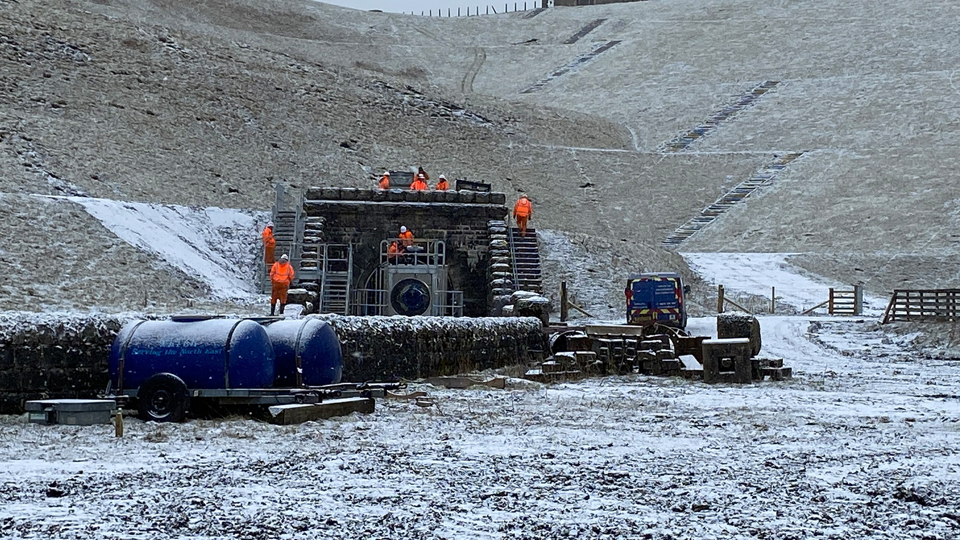

Burnhope Reservoir
Burnhope Reservoir is operated by Northumbrian Water. It is located in the North Pennines AONB (Area of Outstanding Natural Beauty), a UNESCO Global Geopark.
At its deepest, the reservoir is 40m from surface to bed. It has a capacity of around 6.4 million cubic metres.

About Dams & Reservoirs
Learn more about the Dams & Reservoirs segment here, and about how we can assist in your next project.
Go to Dams & Reservoirs